1 Scope
·
Specifications
for structuring the FIPA Interaction Protocol Library (IPL) including a status
of a FIPA Interaction Protocols (IPs), maintenance of the library and inclusion
criteria for new IPs.
·
A description of
how to understand and express IPs using AUML (Agent Unified Modeling Language).
·
The FIPA IP
registry list.
This
specification is primarily concerned with defining the structure of the
FIPA IPL and the requirements for an IP to be included in the
library.
2 Overview
This specification focuses on the organization, structure and status of the FIPA IPL and discusses the main requirements that an IP must satisfy in order to be FIPA-compliant. The objectives of standardising and defining a library of FIPA compliant IPs are:
· To provide tested patterns of agent interaction that may be of use in various aspects of agent-based systems,
· To facilitate the reuse of standard agent IPs, and,
· To express IPs in a standard agent unified modelling language (AUML).
In the following, we present the basic principles of the FIPA IPL which help to guarantee that the IPL is stable, that there are public rules for the inclusion and maintenance of the IPL, and that developers seeking a public IPs can use the IPL.
2.1 Interaction Protocols
Ongoing conversations between agents often fall into typical patterns. In such cases, certain message sequences are expected, and, at any point in the conversation, other messages are expected to follow. These typical patterns of message exchange are called interaction protocols. A designer of agent systems has the choice to make the agents sufficiently aware of the meanings of the messages and the goals, beliefs and other mental attitudes the agent possesses, and that the agent’s planning process causes such IPs to arise spontaneously from the agents’ choices. This, however, places a heavy burden of capability and complexity on the agent implementation, though it is not an uncommon choice in the agent community at large. An alternative, and very pragmatic, view is to pre-specify the IPs, so that a simpler agent implementation can nevertheless engage in meaningful conversation with other agents, simply by carefully following the known IP.
This section of the specification details a number of such IPs, in order to facilitate the effective inter-operation of simple and complex agents. No claim is made that this is an exhaustive list of useful IPs, nor that they are necessary for any given application. The IPs are given pre-defined names and the requirement for adhering to the specification is:
A FIPA ACL-compliant agent need not
implement any of the standard IPs, nor is it restricted from using other IP
names. However, if one of the standard IP names is used, the agent must behave
consistently with the IP specification given here.
These IPs are not intended to cover
every desirable interaction type. Individual IPs do not address a number of
common real-world issues in agent interaction, such as exception handling,
messages arriving out of sequence, dropped messages, timeouts, cancellation,
etc. Rather, the IPs defined in this specification set should be viewed as
interaction patterns, to be elaborated according to the context of the
individual application. This strategy means that adhering to the stated IPs
does not necessarily ensure interoperability; further agreement between agents
about the issues above is required to ensure interoperability in all cases.
Note that, by their nature, agents can engage in multiple dialogues, perhaps with different agents, simultaneously. The term conversation is used to denote any particular instance of such a dialogue. Thus, the agent may be concurrently engaged in multiple conversations, with different agents, within different IPs. The remarks in this section which refer to the receipt of messages under the control of a given IP refer only to a particular conversation.
2.2 Status of a FIPA-Compliant Interaction Protocol
The definition of an IP belonging to the FIPA IPL is normative, that is, if a given agent advertises that it employs an IP in the FIPA Content Language Library (see [FIPA00007]), then it must implement the IP as it is defined in the FIPA IPL. However, FIPA-compliant agents are not required to implement any of the FIPA IPL IPs themselves, except those required for Agent Management (see [FIPA00023]).
By collecting IP definitions in a single, publicly accessible registry, the FIPA IPL facilitates the use of standardized IPs by agents developed in different contexts. It also provides a greater incentive to developers to make their IPs generally applicable.
FIPA is responsible for maintaining a consistent list of IP names and for making them publicly available. In addition to the list of encoding schemes, each IP in the FIPA IPL may specify additional information, such as stability information, versioning, contact information, different support levels, etc.
2.3 FIPA Interaction Protocol Library Maintenance
The most effective way of maintaining the FIPA IPL is through the use of the IPs themselves by different agent developers. This is the most direct way of discovering possible bugs, errors, inconsistencies, weaknesses, possible improvements, as well as capabilities, strengths, efficiency, etc.
In order to collect feedback on the IPs in the library and to promote further research, FIPA encourages coordination among designers, agent developers and FIPA members.
2.4 Inclusion Criteria
To populate the FIPA IPL, setting fundamental guidelines for the selection of specific IPs is necessary. The minimal criteria that must be satisfied for an IP to be FIPA compliant are:
· A clear and accurate representation of the IP is provided using AUML protocol diagram,
· Substantial and clear documentation must be provided, and,
· The usefulness of a new IP should be made clear.
FIPA does not enforce the use of any particular IP.
3 AUML Sequence Diagrams for Interaction Protocol Specification
3.1 Introduction
During
the 1970s, structured programming was the dominant approach to software
development. Along with it, software engineering technologies were developed in
order to ease and formalize the system development lifecycle: from planning,
through analysis and design and finally to system construction, transition, and
maintenance. In the 1980s, object-oriented languages experienced a rise in
popularity, bringing with it new concepts such as data encapsulation,
inheritance, messaging, and polymorphism. By the end of the 1980s and beginning
of the 1990s, a jungle of modelling approaches grew to support the
object-oriented marketplace. To make sense of and unify these various
approaches, an Analysis and Design Task Force was established on 29 June 1995
within the Object Management Group (OMG). And by November 1997, a de jure
standard was adopted by the OMG members called the Unified Modelling Language
(UML - see [OMGuml]).
UML
unifies and formalizes the methods of many object-oriented approaches,
including analysis and design [Booch94 and Booch95], modelling [Rumbaugh91] and
software engineering [Jacobson94]. It supports the following kinds of models:
·
Static
models
Such as class and package diagrams describe the static semantics of
data and messages. Within system development, class diagrams are used in two
different ways, for two different purposes. First, they can model a problem
domain conceptually and since they are conceptual in nature, they can be
presented to the customers. Second,
class diagrams can model the implementation of classes which guides developers.
At a general level, the term class refers
to the encapsulated unit and at the conceptual level, models types and their
associations; the implementation level models implementation classes. While
both can be more generally thought of as classes, their usage as concepts and
implementation notions is important both in purpose and semantics. Package
diagrams group classes in conceptual packages for presentation and
consideration. (Physical aggregations of classes are called components that are in the implementation
model family, mentioned below.)
·
Dynamic
models
These include interaction diagrams (that is, sequence and collaboration
diagrams), state charts and activity diagrams.
·
Use
cases
The specification of actions that a system or class can perform by
interacting with outside actors. They are commonly used to describe how a
customer communicates with a software product.
·
Implementation
models
These describe the component distribution on different platforms, such
as component models and deployment diagrams
·
Object
Constraint Language (OCL)
This is a simple formal language to express more semantics within an
UML specification. It can be used to define constraints on the model,
invariant, pre- and post-conditions of operations and navigation paths within
an object net.
For
modelling agents and agent-based systems, UML is insufficient. Compared to
objects, agents are active because they act for reasons that emerge from
themselves. The activity of agents is based on their internal states, which
include goals and conditions that guide the execution of defined tasks. While
objects need control from outside to execute their methods, agents know the conditions
and intended effects of their actions and hence take responsibility for their
needs. Furthermore, agents do not only act solely but together with other
agents. Multi-agent systems can often resemble a social community of
interdependent members that act individually.
However,
no sufficient specification formalism exists yet for agent-based system
development. To employ agent-based programming, a specification technique must
support the whole software engineering process—from planning, through analysis
and design, and finally to system construction, transition, and maintenance.
A
proposal for a full life-cycle specification of agent-based system development
is beyond the scope of this specification. Here, we suggest a subset of an
agent-based extension to the standard UML, called AUML, for the specification
of agent interaction protocols (AIPs).
It has
to be distinguished between generic (or parameterised) protocols (and their
instantiations) and domain-specific protocols.
3.2 Extending UML by Protocol Diagrams
In the
following, we provide sequence diagrams for AUML [Odell2000], an extension to
UML. We refer to these sequence diagrams as protocol diagrams (PDs) which show well-defined interactions
among agents. Note that we do not define formal semantics for the communicative
acts for AUML, but instead use the UML meta-model.
3.2.1 Protocol Diagrams
Adapted
from [OMGuml], section 3.59.
3.2.1.1 Semantics
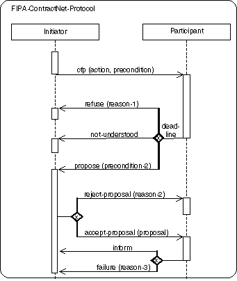
A PD
represents an interaction, which is a set of messages exchanged among different
agent roles within a collaboration to effect a desired behaviour of other
AgentRoles or agent instances.
3.2.1.2 Notation
A PD has
two dimensions: the vertical dimension represents time, the horizontal
dimension represents different AgentRoles. Normally the time proceeds down the
page and usually only time sequences are important, but in real-time
applications the time axis could be an actual metric. There is no significance
to the horizontal ordering of the AgentRoles.
3.2.1.3 Presentation Options
The axes
can be interchanged, so that time proceeds horizontally to the right and
different AgentRoles are shown as horizontal lines.
Various
labels (such as timing marks, generated goals depending on the received
message, etc.) can be shown either in the margin or near the lifelines or
messages that they label.
3.2.1.4 Example
3.2.1.5 Mapping
The
mapping is analogous defined as for sequence diagrams, see [OMGuml].
A PD
maps like a sequence diagram into an Interaction and an underlying
Collaboration. An Interaction specifies a sequence of communications; it
contains a collection of partially ordered Messages, each specifying a
communication between a sender role and a receiver role. Collections of agent
roles that conform to the ClassifierRoles in the Collaboration owning the
Interaction, communicate by dispatching Stimuli that conform to the Messages in
the Interaction. An AgentRole maps into a ClassifierRole. A PD presents one
collection of AgentRoles and arrows mapping to AgentRole and Stimuli that
conform to the ClassifierRoles and Messages in the Interaction and its
Collaboration.
In a PD,
each AgentRole box with its lifeline maps into an agent role that conforms to a
ClassifierRole in the Collaboration. The name fields maps into the name of the
agent, the role name into the Classifier's name and the class field maps into
the names of the Classifier (in this case AgentClasses being Classes) being the
base Classifiers of the ClassifierRole. The splitting of lifelines has a
concurrency Association defining either AND/OR parallelism or decision
Association denoting threads (<<thread>>). The associations among roles are not
shown on the sequence diagram since they must be obtained in the model from a
complementary collaboration diagram or other means. A message arrow maps into a
Stimulus connected to two AgentRoles. the sender and receiver AgentRole. The
Stimulus conforms to a Message between the ClassifierRoles corresponding to the
two AgentRoles' lifelines that the arrow connects. The Link is used for the
communication of the Stimulus and plays the role specified by the
AssociationRole connected to the Message. Unless the correct Link can be
determined from a complementary collaboration diagram or other means, the
Stimulus is either not attached to a Link (not a complete model), or it is attached
to an arbitrary Link or to a dummy Link between the Instances conforming to the
AssociationRole implied by the two ClassifierRoles due to the lack of complete
information. The name of the communicative act is mapped onto the behaviour
associated by the action performing, requested information, information
passing, negotiation or error handling connected to the Message. Different
alternatives exist for showing the arguments of the Stimulus. If references to
the actual Instances being passed as arguments are shown, these are mapped onto
the arguments of the Stimulus. If the argument expressions are shown instead,
these are mapped onto the Arguments of the action performing, requested
information, information passing, negotiation or error handling connected to
the dispatching communicative act. Finally, if the types of the arguments are
shown together with the name of the communicative act, these are mapped onto
the parameter types of the communicative act. A timing label placed on the
level of an arrow endpoint maps into the name of the corresponding Message. A
constraint or guard placed on the diagrams maps into a Constraint on the entire
Interaction. The cardinality label restricts the number of sending and
receiving instances of agent roles accordingly to the numbers denoted at the
beginning (sender) and end (receiver) of the message.
An arrow
with the arrowhead pointing to an AgentRole symbol within the frame of the
diagram maps into a Stimulus dispatched by a CreateAction, that is, the Stimulus conforms
to a Message in the Interaction which is connected to the CreateAction. The interpretation is that the
AgentRole instance (not an arbitrary agent role, nor a set of AgentRole
instances) is created by dispatching the Stimulus, and the AgentRole instance conforms
to the receiver role specified in the Message. After the creation of the
AgentRole instance, it may immediately start interacting with other AgentRoles.
This implies that the creation of the AgentRole dispatches these Stimuli. If an
AgentRole instance termination symbol ("X") is the target of the of
an arrow, the arrow maps into a Stimulus which will cause the receiving agent
role instance to be removed. The Stimulus conforms to a Message in the
Interaction with a DestroyAction attached to the Message or the agent
instance terminates itself.
The
order of the arrows in the diagram map onto a pair of associations between the
Messages that correspond to the Stimuli the arrows maps onto. A predecessor
association is established between Messages corresponding to successive arrow
ends in the vertical sequence. In case of concurrent arrows preceding an arrow,
the corresponding Message has a collection of predecessors. In case of
exclusive-or and inclusive-or arrows preceding an arrow the corresponding message
has one and at least one out of the collection of possible predecessors,
respectively. Moreover, each Message has an activator (thread of interaction)
association to the Message corresponding to the incoming arrow of the
activation or pro-active sending of a message.
A nested
protocol maps into a PD. The name compartment of a nested protocol maps into
the name of the Collaboration. The guard and constraint compartment maps into a
constraint on the complete Interaction.
A
complex nested protocol maps into a PD. The order of the messages within the
protocol is defined according to the combination of the complex nested
protocol. The ordering of the messages in the nested protocol is the ordering
of these protocols. Depending on the combination the messages are sent in
AND/OR parallelism or decision ordering.
3.2.2 AgentRoles
In the
framework of agent oriented programming an agent satisfying a distinguished
role behaves in a special way. In contrast to this semantics role in UML is an instance focused
term. Moreover the term multi-object does not fit to describe AgentRoles but it is used to show operations
that address the entire set, rather than a single object in it. However, there
is a communication with one instance of this multi-object. By AgentRole a set of agents satisfying
distinguished properties, interfaces or having a distinguished behaviour are
meant.
UML
distinguishes between:
·
multiple
classifications where a retailer agent can act as well as a buyer as well as a
seller agent, for example, and,
·
dynamic
classification where an agent can change its classification during its
existence.
Agents
can perform various roles within one IP. Using a contract-net protocol, for
example, between a buyer and a seller of a product, the initiator of the
protocol has the role of a buyer and the participant has the role of a seller.
But the seller can as well be a retailer agent, which acts as a seller in one
case and as a buyer in another case, i.e. agents satisfying a distinguished
role can support multiple classification and dynamic classification. Another
example can be found in [FIPA00023] which defines the functionality of the
Directory Facilitator (DF) and the Agent Management System (AMS). These
functionalities can be implemented by different agents, but the functionality
of the DF and AMS can also be integrated into one agent.
An
AgentRole can be seen as a set of agents satisfying a distinguished interface,
service description or behaviour. Therefore the implementation of an agent can
satisfy different roles.
Note
that within FIPA the notion of role is not used, but in the framework of
specifying agent-based systems this notion is appropriate.
3.2.2.1 Semantics
An
AgentRole describes two different variations which can apply within a protocol
definition. A protocol can be defined between different concrete agent
instances or a set of agents satisfying a distinguished role and/or class. An
agent satisfying a distinguished AgentRole and class is called agent of a given
AgentRole and class, respectively.
3.2.2.2 Notation
An AgentRole
is shown as a rectangle which is filled with some string of one of the
following forms:
·
role
This denotes arbitrary agents satisfying the distinguished AgentRole.
·
instance
/ role-1 ... role-n
This denotes a distinguished agent instance which satisfies the
AgentRoles 1-n where n ³ 0.
·
instance
/ role-1 ... role-n :
class
This denotes a distinguished agent instance which satisfied the
AgentRoles 1-n where n ³ 0 and class it belongs to.
3.2.2.3 Presentation Options
The
second case can be abbreviated as instance if n equals zero, that is, a
concrete agent is meant independent of the role(s) it satisfies and class it
belongs to.
3.2.2.4 Example
![]()
![]()
![]()
![]()
3.2.2.5 Mapping
See Section 3.2.1.5, Mapping.
3.2.3 Agent Lifeline
The
agent lifeline defines the time period when an agent exists. For example a user
agent is created when a user logs on to the system and the user agent is
destroyed when the user logs off. Another example is when an agent migrates
from one machine to another.
3.2.3.1 Semantics
A
PD defines the pattern of
communication, that is, the steps in which the communicative acts are sent
between agents of different AgentRoles. The agent lifeline describes the time
period in which an agent of a given AgentRole exists. Only during this time
period an agent can participate on a protocol.
The
lifeline starts when the agent of a given AgentRole is created and ends when it
is destroyed. The lifeline can be split in order to describe AND/OR parallelism
and decisions and may merge together at some subsequent point.
3.2.3.2 Notation
An agent
lifeline is shown as a vertical dashed line. The lifeline represents the
existence of an agent of a given AgentRole at a particular time. If the agent
is created or destroyed during the period of time shown on the PD, then its
lifeline starts or stops at the appropriate point; otherwise it goes from the
top of the diagram to the bottom. An AgentRole is drawn at the head of the
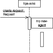
lifeline. If an agent of a given AgentRole is created during the PD, then the
message that creates it is drawn with its arrowhead on the AgentRole. Note,
that the AgentRole (see Section 3.2.3.4, Example) that receives the message is responsible for the creation of the
agent instance, that is, the arrowhead ends at the dashed line of the AgentRole
receiving the message and the AgentRole is fixed at the left-hand or right-hand
side of the lifeline or the thread of interaction. If an agent instance is
destroyed during the PD, then its destruction is marked by a large
"X", either at the message that causes the destruction or (in the
case of self destruction) at the final action of the AgentRole. The termination
is restricted to concrete instances of an agent role.
AgentRoles
that exist when a protocol starts is shown at the top of the diagram (above the
first message arrow). An AgentRole that exists when the protocol finishes has
its lifeline continued beyond the final arrow of the diagram.
The
lifeline may split into two or more lifelines to show AND/OR parallelism and
decisions. Each separate track corresponds to a branch in the message flow. The
lifelines may merge together at some subsequent point. The splitting of the
lifeline for:
·
AND
parallelism starts at a horizontal heavy bar,
·
OR
parallelism (inclusive-or) starts at a horizontal heavy bar with a non-filled
diamond, and,
·
decision
(exclusive-or) starts at a horizontal heavy bar with a non-filled diamond with
"x" inside the diamond.
and is
continued with a set of parallel vertical lifelines connected to the heavy bar.
The
merging is done the analogous way, that is, the parallel vertical lifelines
stop at a some of the horizontal heavy bars and one lifeline is continued from
at the heavy bar.
3.2.3.3 Presentation Options
None.
3.2.3.4 Example
![]()
![]()
![]()
![]()
![]()
![]()
See also Section 3.2.1.4,
Example.
3.2.3.5 Mapping
See Section 3.2.1.5, Mapping.
3.2.4 Threads of Interaction
The
sending of messages can be done either in parallel or as a decision between
different communicative acts. Receiving different communicative acts usually
results in different behaviour and different answers, that is, the behaviour of
an AgentRole depends on the received message.
Adapted
from [OMGuml], section 7.4.
3.2.4.1 Semantics
Since
the behaviour of an AgentRole depends on the incoming message and different
communicative acts are allowed as an answer to a communicative act, the thread
of interaction, that is, the processing of incoming messages, has to be split
up into different threads of interaction. The lifeline of an AgentRole is split
and the thread of interaction defines the reaction to received messages.
The
thread of interaction shows the period during which an AgentRole is performing
some task as a reaction to an incoming message. It represents only the duration
of the action in time, but not the control relationship between the sender of
the message and the receiver. A thread of interaction is always associated with
the lifeline of an AgentRole.
Note we
do not mean a physical thread in this context. The specification is independent
of the implementation using threads or other mechanisms.
3.2.4.2 Notation
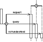
A thread
of interaction is shown as a tall thin rectangle whose top is aligned with its
initiation time and whose bottom is aligned with its completion time. It is
drawn over the lifeline of an AgentRole. The task being performed may be
labelled as text next to the thread of interaction or in the left margin,
depending on the style; alternately the incoming message may indicate the task,
in which case it may be omitted on the thread of interaction itself.
If the
distinction between the reaction to different incoming communicative acts can
be neglected, the entire lifeline may be shown as one thread of interaction.
3.2.4.3 Presentation Options
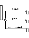
·
Variation
A thread of interaction may can take only a short period of time. To
simplify diagrams, for compactification reasons of the diagram the parallelism
and the decisions can be abbreviated by omitting the splitting/merging and
putting the different threads of interaction one after another on the lifeline.
·
Variation
A break of the rectangle describes a change in the thread of
interaction.
3.2.4.4 Example
 can be abbreviated as
3.2.4.5 Mapping
See Section 3.2.1.5, Mapping.
3.2.5 Messages
The main
issue of protocols is the definition of communicative patterns, especially the
sending of messages from one AgentRole to another. This sending can be done in
different ways, for example, with different cardinalities, depending on some
constraints or using AND/OR parallelism and decisions.
Adapted
from [OMGuml], section 7.5 and section 8.9.
3.2.5.1 Semantics
A
message or sending of a communicative act is a communication from one AgentRole
to another that conveys information with the expectation that the receiving
AgentRole would react according to the semantics of the communicative act. The
specification of the protocol says nothing about the implementation of the
processing of the communicative act.
3.2.5.2 Notation
A
message sending is shown as a horizontal solid arrow from a thread of
interaction of an AgentRole to another thread of interaction of another
AgentRole. In case of a message is sent from an AgentRole to itself (note that
there might be many individual agents in an AgentRole), the arrow may start and
end on the same lifeline or thread of interaction. Such a nested thread of
interaction is denoted by a thread of interaction that is shifted a little bit
to the right side in the actual thread of interaction.
Nested
protocols are represented by a separate thread of interaction, along with an
arrow initiating the nested protocol and one or more arrows terminating the
nested protocol. The initiating arrow
is drawn starting with a small solid filled circle, and a terminating arrow
ends with a circle surrounding a small solid filled circle.
Each
arrow is labelled with a message label which has the following syntax:
predecessor
guard-condition sequence-expression communicative-act argument-list
Where:
·
predecessor
This consists of at most one natural number followed by a slash (/) defining the sequencing of a
parallel construct or the number of the input and output parameter in the
context of Section
3.2.9, Threads
of Interaction and Messages Inside and Outside Nested Protocols, xxxx. The clause is omitted if the list is empty.
·
guard-condition
This is a usual UML guard condition, with the semantics, that the
message is sent iff the guard is true. The guard conditions must be defined on
the behavioural semantics of the agents, that is, the internal state of the
agent must not be used in the definition of the guard.
·
sequence-expression
This is a constraint, especially with n..m which denotes that the message
is sent n up to m times with n Î N, m Î N È {*}[1].
The keyword broadcast
denotes the broadcast sending of a message; the keyword deadline denotes a string that is encoded
according to [ISO8601] and represents the deadline by which a message is
useful.
·
communicative-act
This is either the name, that is, a string representation with an
underlined name, of a concrete communicative act instance, the name of a
concrete communicative act instance and its associated communicative act,
written as name:communicative-act or only the name of the communicative
act, for example, inform.
·
argument-list
This is a comma-separated list of arguments enclosed in parentheses.
The parentheses can be omitted if the list is empty. Each argument is an
expression in pseudo-code or an appropriate programming language or an OCL
expression.
3.2.5.3 Presentation Options
·
Variation:
Cardinality
The cardinality of a message (for example, n senders and m receivers
of a message) is shown by writing natural numbers at the beginning and at the
end of the arrow. This variation is only allowed if the sender and/or receiver
is not an instance of an agent.
·
Variation:
Asynchronous Message Passing
An asynchronous message is drawn with a stick arrowhead (![]() ).
It shows the sending of the message without yielding control.
).
It shows the sending of the message without yielding control.
·
Variation:
Synchronous Message Passing
A synchronous message is drawn with a filled solid arrowhead (![]() ).
It shows the yielding of the thread of control (wait semantics), that is, the
AgentRole waits until an answer message is received and nothing else can be
processed.
).
It shows the yielding of the thread of control (wait semantics), that is, the
AgentRole waits until an answer message is received and nothing else can be
processed.
·
Variation:
Time intensive Message Passing
Normally message arrows are drawn horizontally. This indicates the
duration required to send the message is atomic, that is, it is brief compared
to the granularity of the interaction and that nothing else can take place
during the message transmission. That is the correct assumption within many
computers. If the messages requires some time to arrive for mobile
communication, for example, during which something else can occur then the
message arrow may be slanted downward so that the arrowhead is below the arrow
tail (![]() ).
).
·
Variation:
Repetition
The repetition of parts of a PD is represented by an arrow or one of
its variations usually marked by some guards or constraints ending at a thread
of interaction which is according to the time axis before or after the actual
time point. Note, that in this case the time ordering on the PDs is violated.
3.2.5.4 Example
3.2.5.5 Mapping
See Section 3.2.1.5, Mapping.
3.2.6 Complex Messages
Besides
the already presented kinds of messages, more complex messages can be used.
3.2.6.1 Semantics
A
complex message may be the parallel sending of messages or exclusively sending
of exactly one message out of a set of different messages.
3.2.6.2 Notation
Three
kinds of complex messages are distinguished. All three complex messages
substitute an arrow from one thread of interaction to another thread of
interaction by an arrow starting at one thread of interaction ending either:
·
at
a heavy bar (for AND parallelism),
·
at
a heavy bar with a non-filled diamond (for OR parallelism; inclusive-or), or,
·
at
a heavy bar with a non-filled diamond (for decisions; exclusive-or) with an
"x" inside the diamond.
From
these different kinds of heavy bars new arrows start in a right angle at the
bar and end at possibly different threads of interaction, which are possibly
combined in a parallel or decisional way.
The
merging of different messages is done in the analogous way, that is, the
parallel horizontal message arrows stop at one vertical bar and one message
arrow is continued from the heavy bar.
3.2.6.3 Presentation Options
None.
3.2.6.4 Example


(a) (b)[2] (c)
3.2.6.5 Mapping
See Section 3.2.1.5, Mapping.
3.2.7 Nested Protocols
Nested
protocols are applied to specify complex systems in a modular way. Moreover the
reuse of parts of a specification increases the readability of them.
A nested
protocol can be defined and applied, if it is used several times within the
same specification. In contrast to a parameterised protocol it is only an
abbreviation for a fixed (part of a) protocol. Additionally nested protocols
are used for the definition of repetition of a nested protocol according to guards
and constraints.
Interleaved
protocols show that between different agents a protocol is performed and more
over in order to finish/proceed the protocol an agent has to perform another
protocol with other agents.
3.2.7.1 Semantics
If the
nested protocol is marked with some guard then the semantics of the nested
protocol is the semantics of the protocol under the assumption that the guard
evaluates to true, otherwise the semantics is the semantics of an empty
protocol, that is, nothing is specified.
If the
nested protocol is marked with some constraints the nested protocol is repeated
as long as the constraints evaluate to true.
3.2.7.2 Notation
A nested
protocol is shown as a rectangle with rounded corners. It may have one or more
compartments. The compartments are optional. They are as follows:
·
Name
compartment
This holds the (optional) name of the nested protocol as a string.
Nested protocols without names are anonymous.
It is undesirable to show the same named nested protocol twice in the
same diagram except when they define the same nested protocol. The compartment
is written in the upper left-hand corner of the rectangle.
·
Guard
compartment
This holds the (optional) guard of the nested protocol in the usual
guard notation as [guard-condition]. Nested protocols without guards are
equivalent with nested protocols with guard [true]. The guard compartment is
written together with the constraint compartment in the lower left-hand corner
of the rectangle.
·
Constraint
compartment
This holds the (optional) constraint of the nested protocol in the
usual constraint notation as {constraint-condition}. Nested protocols without constraints are
equivalent with nested protocols with constraint {1}. The constraint compartment is
written together with the guard compartment in the lower left-hand corner of
the rectangle. In addition to the constraint condition used in UML the
constraint n..m denotes
that the nested protocol is repeated n up
to m times with n Î N, m Î N È {*}.
Another
nested protocol can completely be drawn within the actual nested protocol
denoting that the inner one is part of the outer one.
3.2.7.3 Presentation Options
The
abbreviations n and * can be applied to denote n..n and 0..*, respectively. Beyond the above usage of nested protocols for
simple protocols, nested protocols can also be used applying parameterised
protocols or instantiated parameterised protocols.
Another presentation option is the definition of interleaved protocols. For a nested protocol being part of another protocol the rectangle representing it has to be completely drawn within the other one. If interleaved protocols are defined, that is, during performing one IP another IP has to be processed, the rectangles are not drawn within each other.
3.2.7.4 Example
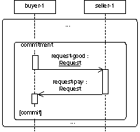
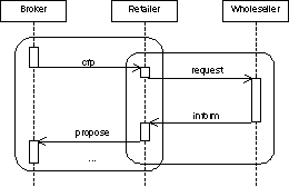
Nested Protocol Interleaved Protocols
3.2.8 Complex Nested Protocols
Beyond the already presented nested and interleaved protocols, other kinds of complex nested protocols can also be defined.
3.2.8.1 Semantics
A complex nested protocol defines the parallel or decisional combination of nested protocols. It has to take into consideration the thread of interaction at the beginning and at the end of the complex nested protocol. Furthermore the starting and ending point within the nested protocols have to be considered.
3.2.8.2 Notation
Three kinds of complex nested protocols are distinguished. All three complex nested protocols are drawn over the lifeline and threads of interaction within a PD. Each individual nested protocol in a complex nested protocol is introduced by a line that is terminated by the rectangle of a nested protocol. These lines are connected either by:
· a heavy bar defining AND parallelism,
· a heavy bar with a non-filled diamond defining OR parallelism (inclusive-or), or,
· a heavy bar with a non-filled diamond defining decisions (exclusive-or) with an "x" inside the diamond.
The threads of interaction which are continued in the different nested protocols are drawn as usual.
3.2.8.3 Presentation Options
None.
3.2.8.4 Example
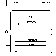
3.2.8.5 Mapping
See Section 3.2.1.5, Mapping.
3.2.9 Threads of Interaction and Messages Inside and Outside Nested Protocols
Usually, nested protocols have input and output parameters, namely threads of interaction and messages.
3.2.9.1 Semantics
Nested protocols are defined in detail either within a PD where it is used or outside another PD. Threads of interaction and messages inside and outside nested protocols define the input and output parameter for nested protocols.
The input parameters are the threads of interaction, which are carried on in the nested protocol, and the messages which are received from other IPs.
The output parameters are on the one side the threads of interaction which are started within the nested protocol and are carried on outside the nested protocol and the messages which are sent from inside the nested protocol to AgentRoles not involved in the actual nested protocol. A message or thread of interaction ending at an input or starting at an output parameter of a nested protocol describes the connection of a whole PD with the embedded nested protocol.
3.2.9.2 Notation
The input and output parameters for the threads of interaction of a nested protocol are shown as a tall thin rectangle (like a thread of interaction) which is drawn beyond the bounds of over the top line and bottom line of the nested protocol rectangle, respectively.
The input and output message parameters are shown by arrows starting with a small solid filled circle, and arrows ending at a circle surrounding a small solid filled circle (a bull's eye), respectively.
3.2.9.3 Presentation Options
The message arrows can be marked like usual messages. In this context, the predecessor denotes the number of the input/output parameter. The input/output thread of interaction can be marked with natural numbers to define the exact number of the parameter.
3.2.9.4 Example
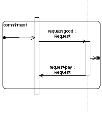
3.2.9.5 Mapping
See Section 3.2.1.5, Mapping.
3.2.10 Parameterised Protocols
Adapted from [OMGuml], section 5.11.
3.2.10.1 Semantics
A parameterised protocol is the description for an IP with one or more unbound formal parameters. It therefore defines a family of protocols, each protocol specified by binding the parameters to actual values. Typically the parameters represent agent roles, constraints, instances of communicative acts and nested protocols. The parameters used within the parameterised protocol are defined in terms of the formal parameters so they are become bound when the parameterised protocol itself is bound to the actual values.
A parameterised protocol is not a directly-usable protocol because it has unbound parameters. Its parameters must be bound to actual values to create a bound form that is a protocol.
3.2.10.2 Notation
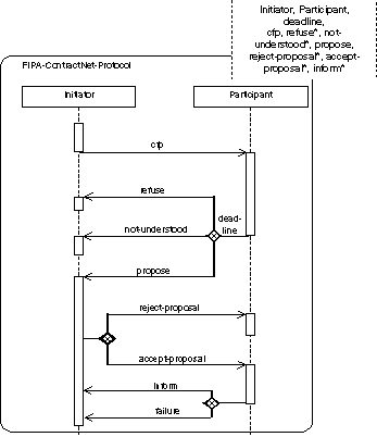
A small dashed rectangle is superimposed on the upper right-hand corner of the rectangle with rounded corners as when defining a nested protocol. The dashed rectangle contains a parameter list of formal parameters for the protocol. The list must not be empty, although it might be suppressed in the presentation. The name of the parameterised protocol is written as a string in the upper left-hand corner.
The parameter list is a comma-separated list of arguments (formal parameters) defined by identifiers, like names for AgentRoles, constraint expressions, communicative acts or nested protocol names.
3.2.10.3 Presentation Options
The input/output parameters like messages and threads of interactions can be used and defined as for nested protocols.
Communicative act can be marked with an asterisk in the parameter specification, denoting different kinds of messages that can alternatively be sent in this context.
3.2.10.4 Example
3.2.10.5 Mapping
See Section 3.2.1.5, Mapping.
3.2.10.6 Comment
Note the difference between interleaved, nested and parameterised protocols. An interleaved protocol is used to show that during the execution of one protocol another one is started/performed. Nested protocols are used to show repetitions of sub-protocols, identifying fixed sub-protocols, reference to a fixed sub-protocol, like asking the DF for some information, or guarding a sub-protocol. Parameterised protocols are used to prepare patterns which can be instantiated in different contexts and applications, for example, the FIPA Contract Net Protocol for appointment scheduling and negotiation about some good which should be sold.
3.2.11 Bound Elements
Adapted from [OMGuml], section 5.12.
3.2.11.1 Semantics
A parameterised PD cannot be used directly in an ordinary interaction description, because it has free parameters that are not meaningful outside of a scope that declares the parameter. To be used, a formal parameter of a parameterised protocol must be bound to actual values. The actual value for each parameter is an expression defined within the scope of use. If the referencing scope is itself a parameterised protocol, then the parameters of the referencing parameterised protocol can be used as actual values in binding the referenced parameterised protocol, but the parameter names in the two templates cannot be assumed to correspond, because they have no scope outside of their respective templates. We can assume without loss of generality that the parameter names of the different parameterised protocols are different.
3.2.11.2 Notation
A bound element is indicated in the name string of an element, as follows:
parameterised-protocol-name < role-list, constraint-expression-list,
value-list >
Where:
· parameterised-protocol-name
This is identical to the name of the parameterised protocol.
· role-list
This is a comma-delimited list of role labels. constraint-expression-list is a comma-delimited list of constraint terms.
· value-list
This is a comma-delimited non-empty list of pairs, separated by a colon consisting of a value expression and a communicative act. The communicative act is optional.
The number and types of the values must match the number and types of the parameterised protocol formal parameters for the parameterised protocol of the given name. The bound element name may be used anywhere that protocol of the parameterised kind could be used.
3.2.11.3 Presentation Options
None.
3.2.11.4 Example
FIPA-ContractNet-Protocol
<
Buyer, Seller
20000807
cfp-seller : cfp,
refuse-1
: refuse,
refuse-2
: refuse, not-understood, propose, reject-proposal, accept-proposal,
cancel, inform, failure
>
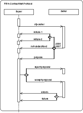
3.2.11.5 Mapping
The use
of the bound element syntax for the name of a symbol maps into a Binding
dependency between the dependent ModelElement corresponding to the bound
element symbol and the provider ModelElement whose name matches the name part
of the bound element without the arguments. If the name does not match a
parameterised protocol or if the number of arguments in the bound element does
not match the number of formal parameters in the parameterised protocol, then
the model is ill-formed. Each argument in the bound element maps into a
ModelElement bearing a templateArgument association to the Namespace of the
bound element. The Binding relationship bears the list of actual argument
values.
4 References
[Booch94] Booch, G., Object-Oriented Analysis and
Design with Applications. Benjamin/Cummings, 1994.
[Booch95] Booch, G., Object Solutions: Managing
the Object-Oriented Project. Addison-Wesley, 1995.
[FIPA00007] FIPA Content
Language Library Specification. Foundation for
Intelligent Physical Agents, 2000. http://www.fipa.org/specs/fipa00007/
[FIPA00023] FIPA Agent
Management Specification. Foundation for Intelligent
Physical Agents, 2000. http://www.fipa.org/specs/fipa00023/
[ISO8601] Date Elements and Interchange Formats, Information Interchange – Representation of Dates and Times, ISO 8601:1988(E), 1988.
[Odell2000] Odell, J., Parunak, H. van Dyke and Bauer, B., Extending UML for Agents. In: AOIS Worshop at AAAI, 2000.
[OMGuml] OMG Unified Modelling Language Version
1.1, Object Management Group, 1999.
http://www.omg.org/uml/
[Rumbaugh91] Rumbaugh, J., Blaha, M., Premerlani, W., Eddy, F. and Lorenzen, W., Object-Oriented Modeling and Design. Prentice Hall, 1991.